Locomotives -
Operational Locos -
Locos under overhaul -
Locos on static display -
Locos formerly based on the Bluebell
Loco Roster -
Loco Stock List -
Loco Works News -
Join the Loco Dept
Atlantic Project - Background - Completion and launch - Next Projects: 'Normandy' and the Adams Radial Tank


Bluebell Railway Atlantic Group
2013 progress


January 2013
Fred Bailey supplied this update and photos early on in the year, so apologies for the delay in preparing the page. Fred hopes we can appreciate that there is not a lot "big" to photograph, but the update shows lots of important (and hopefully interesting) smaller items, all steps on the way to major progress.
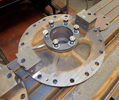
Right: Rear cylinder cover fully machined with the exception of the large tapped hole for the relief valve, which is to be done after the cylinder assembly pressure test.
As it is some time since we have updated our web pages I thought I ought to offer a few words of explanation. We have been steadily working on the project despite the lack of wheels. As to these items, there have been a few production problems with them, that have delayed their completion, but we think that these are now resolved and hopefully they should soon be finished and delivered. It is only the shrinking in of the crankpins with their keys and the final seal welding that needs to be done to finish the job in its entirety.
A lot of the work in Atlantic House is not very visible, being the manufacture of small special vital parts that will be needed in order for us to assemble the valve gear, slide-bars etc. Four of the more major parts that have been the completed are the front and rear cylinder covers. This has allowed us to seal off all holes in the cylinders and valve chests and put a pressure test on the whole assembly mainly to prove the sealing arrangements between the cylinders and the valve chests. The cylinders and their seals are some-what unusual and are not the same as used for standard cast construction, so we had to check on their integrity before fitting the final bolts that hold the whole lot together. Fortunately this test, conducted at the end of the year was a success, so the final fitted bolts may now be installed. Included in this work was the careful alignment of the intermediate valve spindle guide. This was installed so that a close fitting bar could pass through not only the guide bushes, but both the front and back valve chest covers. Close alignment over more than 6 feet - not easy. This however is now in its final position and just needs the final fitted bolts installing.
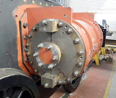
Above: The rear cylinder cover bolted to the cylinder, and inner lagging plates being trial fitted. There are also outer "decorative" covers that will go over the whole lot, but they really need to be spun to shape; tooling for that operation is a little expensive.
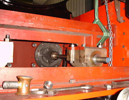
The second photo shows the alignment bar passing through the intermediate valve spindle guide bushes and disappearing through the rear valve chest cover, ending up in the bush in the front valve chest cover. The whole stretcher had to be lifted, twisted and finally clamped in position while still allowing the close fitting bar to be turned by hand or slid in and out through the bushes before drilling through from the frames and fitting the final fitted bolts.
As to valve gear parts, most of these are at present being machined by our sub-contractor in the Midlands, but we have now received the expansion links and die blocks, wire eroded out of a tough grade of steel and then nitrided to produce a glass hard surface for wear resistance. These were produced by a small local machine shop, Epal Ltd. of Storrington. The die blocks fit so that they slide freely along the curved slot without a vestige of slop. Most impressive!
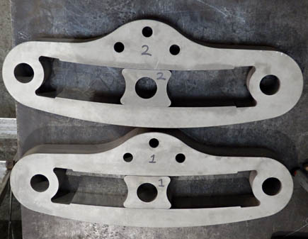
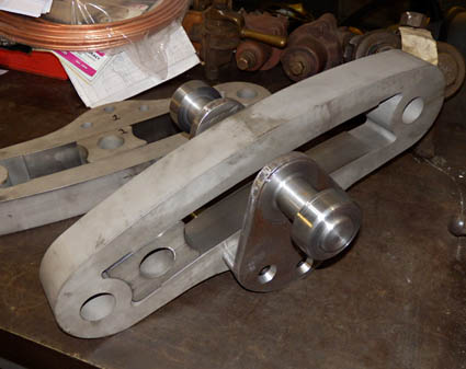
Above: The wire eroded and hardened expansion links, and in the second photo, these expansion links with the lifting brackets produced in Atlantic House being trial fitted. The three fixing holes are all very carefully jig bored and then on assembly have close fitting pins passed through them. The ends of these pins are riveted over into the countersinks to retain them. The fit of the pins ensures the suspension pin parts of the bracket are exactly opposite each other.
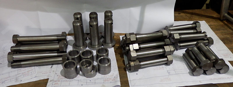
Below: All these special pins - for brake blocks and slidebar bolts etc. - produced by our volunteer machinist, Malcolm Place.
7 March 2013
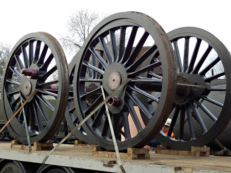
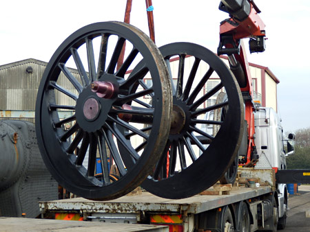
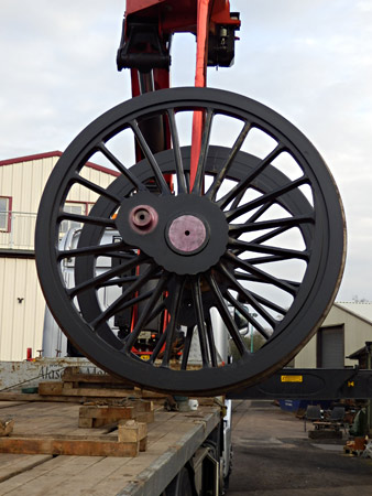
At last they are here!
Here are a few photos taken by Fred Bailey first thing yesterday morning when the Atlantic driving wheels were delivered. When seen 'in the flesh' they look huge - they are over 6'9" over the flanges.
The photo of the driving set (above right) clearly shows the unusual eccentric crankpin. The leading wheelset, with a much smaller balance weight, is seen in the photo immediately to the right.
At least the question everyone asks will change now. "When will the chassis be wheeled?" At this time there isn't an honest answer other than "Once we are satisfied that we have completed all the work between the frames that is best carried out while we still have reasonable access." One thing we do not have in Atlantic House is a pit, although even that would be of limited help; like a lot of locomotives there is more engineering between the frames than on the outside.
Atlantic House will be open with a sales stand, and the chance to get a closer look and discuss progress, for several days over the extension opening week. The intended 'open' days are 23, 24, 28, 29, 30 & 31 March and 1 April.
May 2013
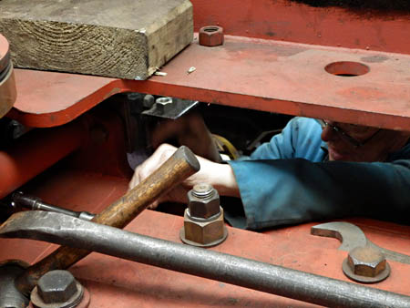
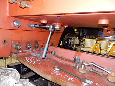
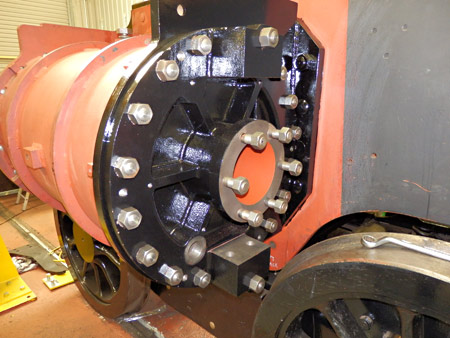 More good progress to report on the construction of the Brighton Atlantic. We now have the cylinders fitted to the frames with the proper fitted bolts. This has been quite a long process involving the gradual reaming out of each hole to produce a good clean surface in each of the 3 thicknesses of material totaling about 3 and 3/16 of an inch (81mm). Due to access problems (see photos below) this has had to be done by hand with a 1/2" square drive socket set ratchet driving an expanding reamer, slowly! The result is important as it ensures that the driven bolts are in close contact with all relevant parts of the assembly. There is a lot of force on a 20" diameter piston at 170 psi steam pressure, alternating back and forth just trying to wrench the cylinders from the frames.
The rear cylinder covers have also now been fitted and work is now concentrating on the fitting up of the slide-bars and motion brackets. The photo on the right shows the rear cylinder cover now finally fitted to cylinder, which in turn is bolted to the frames with the fitted bolts. (All photos and text for this report are from Fred Bailey.)
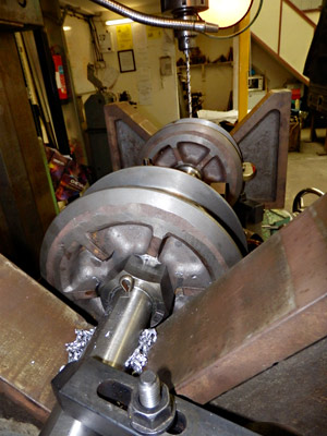
The two photos below show some of the difficulty of working in a confined space - reaming holes for the cylinder fitted bolts. In the second, access here is not quite so cramped, but this view is of the same process on the underside of the valve chest, with the bogie stretcher below.
 Assembly of the valves is now almost complete and we will soon be able to install these in the valve chests. We have also now received the guided intermediate valve spindles and the valve extension rods. With all of these parts we should be able to shortly look at fitting the weigh shaft.
The photo on the right shows the valve heads, after being set the correct distance apart by the use of shims, having the shafts cross drilled to fit pins to prevent the nuts slacking back. This procedure governs the exhaust clearance and other vital dimensions to do with obtaining the correct valve events.
The boiler is making good progress with over half of the patch screws fitted in the lap seams in the inner firebox and all the tapped holes in the firebox tubeplate are now tapped out ready to receive the threaded ends of the supeheater flues. The bottle ends for these are due to be delivered any day soon. There is quite a lot of machining required on these before they can be welded to the flues themselves. These are not on order due to space considerations.
Work is also proceeding on the Westinghouse pump renovation and also the Gresham and Craven brake ejector.
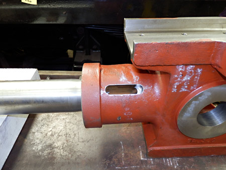
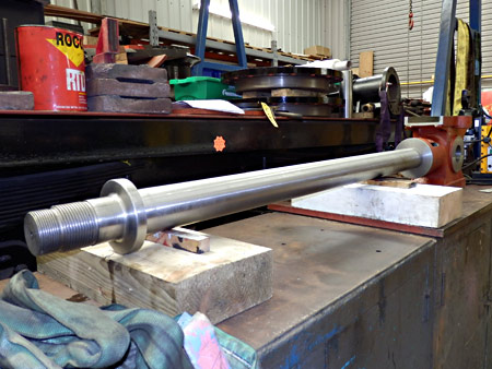
Below we see the valve extension rods, just received from Unilathe Ltd. These were machined from forgings and look to be a nice piece of work. They were very expensive however! The first picture fore-shortens them some-what; they are 5 feet long.
The second shows the rear end of the valve extension rods. We await yet more parts, so watch this space.
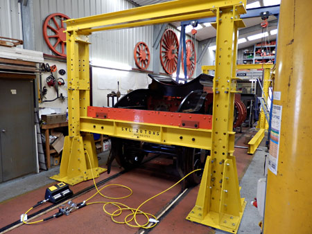 We have had a long hard look at the problems and expenses involved in the lifting of the chassis for wheeling and other purposes and came to the conclusion that having our own equipment would be the best option. Crane hire is expensive especially if things do not go to plan. Access to our chassis would involve laying a trackway at right angles to the main access road for visiting rolling stock and of course coal lorries. This will of course need to be done later for fitting the boiler. The purchase of commercial equipment is very expensive and vehicle lifting jacks take up too much room and will not fit in the available space, hence our designing and building our own equipment to do the job. All the Enerpac jacks with their air driven hydraulic pumps are new.
The design is similar to a large bush press and allows us to lift the chassis in about 7" stages. When the height limit of the rams is reached, the beams holding the chassis are settled on to the pins in the side frames, the jacks lowered, the plates beneath them raised onto pins placed in the higher holes and the process repeated. Probably quicker to do than to write about! These lifting frames will of course be available in the future for use under the next new build project (possibly a Craven era loco as shown in the long term plan) or under a smaller locomotive undergoing repair or restoration. These frames can, if required, be flat packed and re-assembled at a later date, all parts being numbered to aid in assembly.
 The photo on the right shows the front lifting frame with the cross beam bolted to the buffer beam ready to lift. In due course, to get the driving wheels in, the chassis needs to be raised by 4 feet.
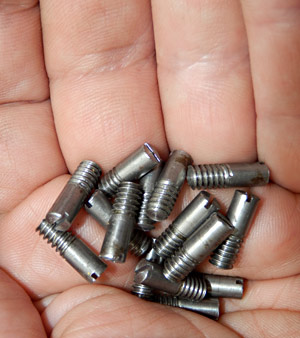
In working order the loco weighs in excess of 68 tons, but not all the bits are heavy! These 16 hand made 3/16" Whitworth screws (left) are fitted in the valve heads, under the rings. These are exactly as shown on the original drawings of GWR (yes, another bit of Great Western on the Bluebell!) semi plug valves, which are used on this design of engine.
In short a lot is happening on a lot of fronts.
If you'd like to support the project by sponsoring a specific part of the locomotive - please see the updated component list. See also other ways to support the project.
Early August 2013
Update and photos from Fred Bailey:
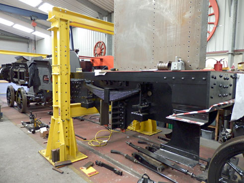
The first photo shows the slidebar brackets, now finally fitted to the frames, and the slidebars being fitted in place. Along with these, the stretcher holding the brake cylinders (unseen between the frames) is also now finally bolted into position.
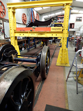
As seen below, we've been making use of the new lifting frames:-
- In order to gain access to the valve chest area the chassis has been lifted and the bogie wheeled out.
- To keep things level, the rear has been lifted at the same time, and the trailing wheels have been removed as we have some minor jobs to complete at this end as well.
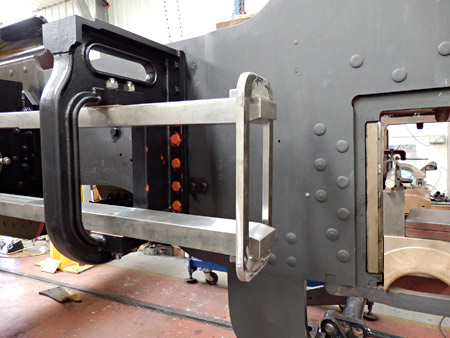
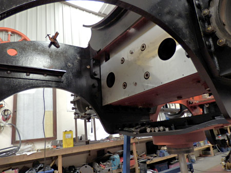 This photo on the right shows that we are starting to fit the valve chest lagging plates. These are made from stainless steel to fight the inevitable corrosion.
Drawings of the pipework are in a fairly advanced stage, so we should soon be able to start on the pipe runs between the frames. There are a lot of pipes to consider, the largest being 2" steel for the vacuum train pipe, followed by 1.5" steel for the steam heat and then a number of smaller ones connecting the pump and the air reservoir to the air brake control equipment. All of these have to be routed above the axles, and below the valve chests. They must also avoid the firebox, ashpan, damper and drain cock operating rods and levers, plus of course the reach rod which is also run through the limited space available. The rear of the drag box will be a bit congested as these also pass between the engine and the tender. To these must be added the injector water feeds. Probably a total of 7 connections.
The renovation of the Westinghouse pump and the other parts of the system are all progressing well, but not as yet very photogenic.
We hope to start machining the pistons and the crosshead slippers shortly, once we receive the piston rods and crossheads from the sub-contract machine shop who, as is usual, are excessively late on delivery.
Late August 2013
A second engineering update this month, together with photos, from Fred Bailey:
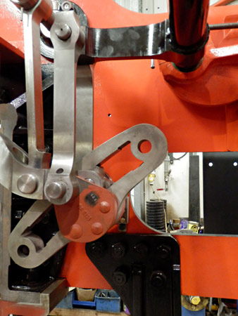
To the right we see preliminary work installing the Stephenson valve gear. The idea was to finalise the reversing shaft position, but on getting to the stage shown, we have found that we have too many variables to allow us to fix the height accurately, so will finish the job once we have the driving wheels and eccentrics installed. A dimension is given on the drawings, but it is quoted down to 32nds of an inch and comes from a point in space i.e. the centre line of the axles. This position is too critical to the valve events to risk getting it wrong.
The design of a set of valve setting rollers is being finalised at present, and should enable us to turn the driving wheels slowly and with (I hope) little effort.
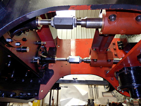
The first photo below shows the valve adjusters. A fine adjustment of the valve position should be possible using these. The threads in the large nuts are both right handed, but of different pitches. The movement of the valve is the difference between the pitches of the two threads. Nothing new here - a combination of GWR practice and the table stops on our workshop milling machine! The valves are fully assembled and the valve chest covers are finally fitted.
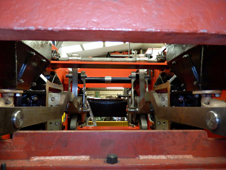
The next photo below provides a view looking towards the rear between the frames. The two intermediate valve rods with the sets to avoid the leading axle figure prominently.
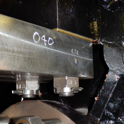
 Some small details that make a difference, and one reason things take the time they do! The photo on the left at first glance just shows a nut and bolt. These are the slidebar fixings. The bolts were made in Atlantic House as they are 1" Whitworth of a non standard length. The castellated nuts have been skimmed to improve their appearance - not a long job. The shim made out of brass is on the original drawings and helps with setting the distance between the slidebars accurately. Ours are less than .002" out of parallel along the length of travel of the crosshead a distance of about 40". (Stroke of piston plus length of crosshead top slipper). Back to the bolts. To fit these, they have to be tapped through the close fitting hole, the nut fully tightened as usual using a copper mallet on the ring spanner - no fancy torque settings on steam locos! The bolt is then marked by drilling through one of the slots (that is accessible) with a pistol drill. The nut is then undone and the bolt removed and both items stamped with identifying letters and numbers so that in the future the nuts will tighten at the point that the hole in the bolt aligns with the slot in the nut. The bolt is set up in the machine vice on the milling machine and accurately drilled exactly through the centre starting in the mark made earlier. The thread deburred from the drilling and the whole fitting procedure repeated. When finally happy that the assembly need not be broken down the split pin will be shortened, fitted and the legs opened. Now repeat for the next 15 bolts!
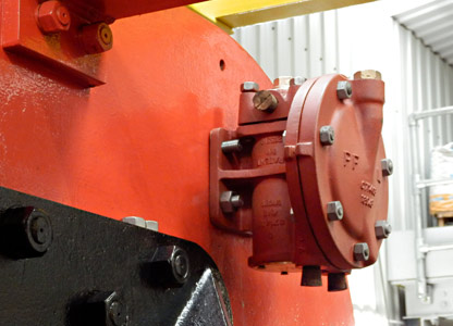
Below is the partially renovated Westinghouse Brake proportional valve in the process of being fitted to the mainframe.
Early September 2013
10th September saw a visit to the Bluebell on a railtour of new-build LNER A1 Pacific 60163 "Tornado". Atlantic House was open that day, and our own project was the subject of much interest, whilst Tornado was in the loco yard, being serviced. The two locomotive designs of course share a common ancestry from the GNR.
Thanks again to Fred Bailey, we have another engineering update:
On the right we see one of the pair of crossheads complete with gudgeon pin, received just about 15 months late, but fortunately once again we ordered far enough in advance that we ended up with a "just in time" delivery. These are being carefully scrutinised at present, and so far they have been found to be adequate. We now have to machine all the bronze slippers that fit to these basic parts, then white-metal them and re-machine to fit them to the slidebars and so obtain the correct running clearances.
The first photo below shows a trial fit of the piston rod in the crosshead, conducted in the main to check on both the fit of the tapers and also the "draw" left in the slot to allow the cotter, when fitted, to both pull the parts together and lock them in place. This is a little tricky to get right but they look to be good.
The next shows, near the camera, the piston end of the piston rod with its different sizes of thread. The larger thread is right handed and the smaller one left handed. The nuts are being made in Atlantic House, and when fitted the two nuts are locked to each other with a tab washer. This feature is copied from BR standard loco practice. You may notice the crosshead at the far end.
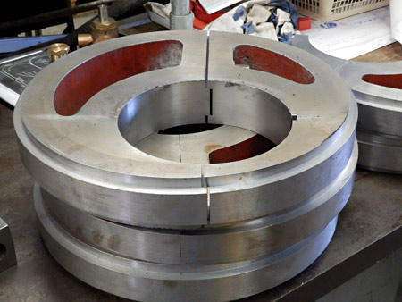
 We now also have the four eccentrics (left), machined from our free-issued castings by TMA Ltd. in Birmingham. The top one on this stack is separated slightly to show the joint between the two halves. All of these have been inspected and all of these were machined well within the drawing tolerances.
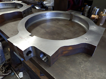
To go with these, again machined by the same company from our free issue castings, are the four eccentric straps, one of which is shown below. Again, all of them a first class job.
Not shown here are many lengths of heavy-weight steel pipe and bags of heavy-weight fittings ready for us to start piping up the air braking system. Work has also started on putting in the small copper pipes linking the greasing manifolds to the hollow bolts in the horn guides. Hopefully some pictures of this work with the next update.
December 2013
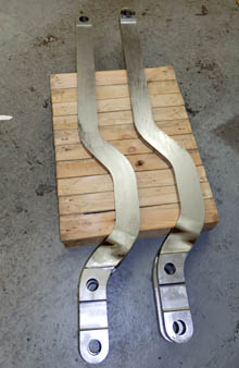
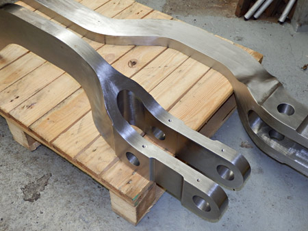
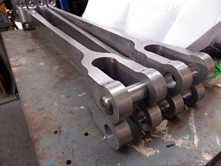
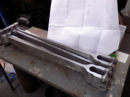
At last we have received our Christmas presents from Unilathe! The four Eccentric Rods arrived for us to unwrap on Sunday 22nd. We now have all the major parts to complete the valve gear.
Although all apparently minor detailed work, progress recently has been good, with most of the major steel pipes now at least temporarily fitted between the rear of the valve chests and their positions to the rear of the ashpan. All of the drain cocks have been fitted up with their operating rods and levers and, at least in the cold, work well; only when hot will we be sure!
Work is now under way doing the final machining of the driving and coupled axle-boxes. We have also now found a solution to the problem of how to fix the weigh (or reversing) shaft in its correct position, and work is proceeding in making up the fixtures required to carry out this work. The wheel rotators to be used for setting up the crankpin and keyway positions and later for valve setting are also well in hand.
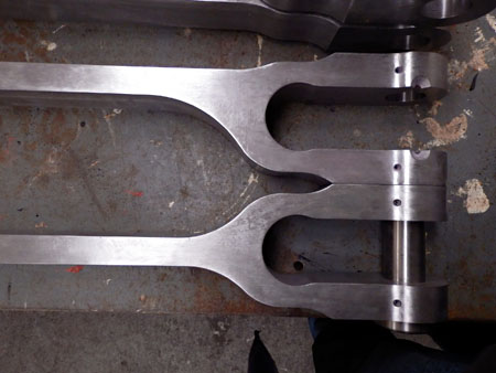
At present although progress is good it is not very photogenic, but this will come later. However here are some photos from Fred Bailey of the eccentric rods. They are well machined and look very good, so for once we are guardedly happy!
- That on the right and the first below show all four rods. They are placed so that the front offset ends are in line top to bottom as fitted to the expansion link, with the far end separated where they fit to the eccentric straps.
- The second photo below shows the difference in the offsets at the expansion link ends of the rods. The bottom one is a fore gear rod and the top a reverse gear rod.
If you fancy helping us out, we still need to raise a lot of money to complete the locomotive. The component sponsorship list was updated a couple of months back; if you fancy sponsoring the cost of a pair of eccentric straps, we have them available at £500 a pair. If that's beyond your budget, we also need some copper firebox patch screws, which are just £20 each.
The Bluebell Atlantic Team wish their supporters a very happy New Year.


More recent news updates
- 2014 - Weigh (reversing) shaft and air-clutch fitted, axleboxes metalled, machined and fitted, wheel rotators constructed, eccentric rods, valve and reversing gear, pipework for brakes and steam heat completed, locomotive wheeled, cylinders clad and crossheads fitted.
- 2015 - Rolling Chassis completed with all motion erected. Running plates and splashers completed, along with cab sides and front.
- 2016 - Connecting and coupling rods fitted, valves set. Superheater header delivered. Revision of boiler internal pipework completed. Cab roof riveted together and fitted. Mud-hole patches welded into boiler. Flue tubes (with screw ends welded on) delivered.
- 2017 - Major progress on the boiler overhaul, and with the safety valves.
- 2018 - Boiler tubes fitted, tender made mobile, complex parts of the boiler cladding made.
- Most recent news.
Older news updates
- Background and early progress
- September 2001: Repairs to tender chassis.
- More photos of the project (1999-2002).
- March 2002: Modification of front end of tender.
- November 2004: Loco Frames ordered.
- December 2004: Bogie frame components arrive - also Feb.2005 news report.
- 2005 - Loco main frames arrive - tender frames nearly completed - start of construction of the shed.
- 2006 - Loco driving wheel castings delivered - drilling of the main frames and hornguides - building of the shed completed.
- 2007 - Main locomotive frames erected.
- 2008 - Components for the cylinders and valve chest delivered - frames riveted - forged billets for connecting and coupling rods delivered.
- 2009 - First motion parts water-jet cut from forged blanks - bogie frames assembled.
- 2010 - Cylinders and valve chests fabricated, air brake cylinders completed, bogie and trailing wheelsets completed.
- 2011 - Coupling rods and axleboxes delivered, reverser mechanism completed, crossheads cast.
- 2012 - Valve and cylinder liners fitted - lifting and reversing arms and axlebox crowns delivered - castings for mudhole doors, regulator and whistle valves, reversing shaft clutch, blast-pipe cap, crosshead slippers, 'J' pipe and eight eccentric halves received - Bogie and trailing axle now support the frames - Valve chest and cylinders fitted to frames, covers fitted, and pressure tested.
Project Funding
A fund raising appeal for the cash required to complete the project was launched in 2000, and a combination of gifts made via the Bluebell Railway Trust, and standing orders set up to provide a steady income to the project have now made over a third of the total available. Whilst this has provided funding for the present work, more is going to be needed to complete the project, and the best way in which you can help is by setting up a small, regular, standing order to the Bluebell Railway Trust under Gift Aid, since this enables the Trust to reclaim the basic rate tax you have paid, and (if you are a higher rate tax-payer) enables you to reclaim some tax as well.


Return to BRPS Home Page,
to the Timetable or to Special
Events
Atlantic Project - Background - Completion and launch - Next Projects: 'Normandy' and the Adams Radial Tank
Visitor Info. -
Museum -
Trust -
Catering -
Contacts -
What's New -
Projects -
Locos -
Carriages & Wagons -
Signals -
History -
Other -
Links -
Search -
FAQ
Why not become a BRPS Member? -
Get more involved as a Volunteer
Your ideal Film/TV location?
 Photos and reports from Fred Bailey.
Page maintained by Richard Salmon
© Copyright BRPS. Privacy Policy
|
