Locomotives -
Operational Locos -
Locos under overhaul -
Locos on static display -
Locos formerly based on the Bluebell
Loco Roster -
Loco Stock List -
Loco Works News -
Join the Loco Dept
Atlantic Project - Background - Completion and launch - Next Projects: 'Normandy' and the Adams Radial Tank


Bluebell Railway Atlantic Group
2009 progress


9 April 2009
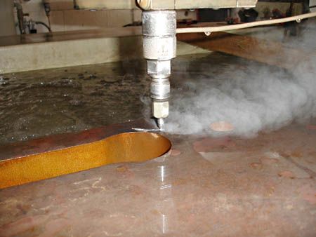
Fred Bailey's photo on the right shows that the abrasive water-jet cutting of the motion parts has now started. We are using a small local firm to carry out this work so that we can work together with them on this project. The material is 4,1/2" thick steel, cut using 50,000 psi water together with fine garnet powder. Each of these relatively small lifting links takes about 5 hours to cut. The outside profile being "decorative" is cut to finished size plus 0.020" to allow for hand finishing.
The remaining pictures are thanks to Malcolm Place.
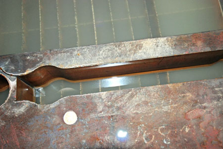
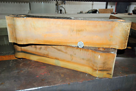
The first picture below shows the hole left in the forged billet after the removal of one of the lifting links. The other photo below shows two lifting links with a 50p coin standing on one. We are hoping to turn these through 90 degrees and profile in the other direction as well. This is not commonly done, but we have some ideas to try and sufficient material to experiment with.
The picture on the right actually shows the jet starting to cut the third of the lifting links, so really follows the other two chronologically.
Shortly we hope to move on to the first of the coupling rods. These will be cut in one plane only as we need to get these machined and fluted on the side faces and there would be little to be gained from the extra water-jet cutting.
23 April 2009
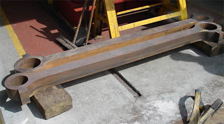
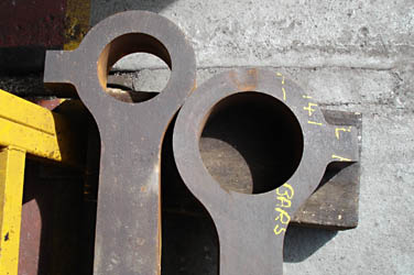
Fred Bailey's photos show that the coupling rods have now been delivered, and the first work is being carried out on the fabricated valve chests and cylinders.
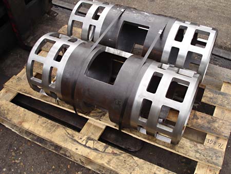
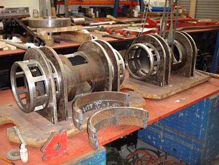
On the right we see the valve chest liner support tubes, and below a trial assembly of valve chests, and a closer view of valve chest liner support tube assembly, showing tab and slot construction.
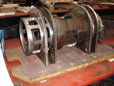
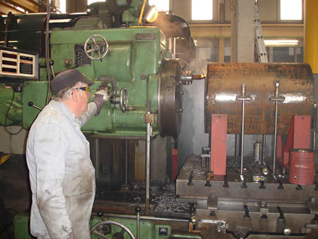

Here we see Derek Barlow using the Kearns borer to face, weld prep, and cut ports in one of the main cylinder-liner support tubes.
Below are the newly cut coupling rods, and a close-up of the rod ends.
25 June 2009
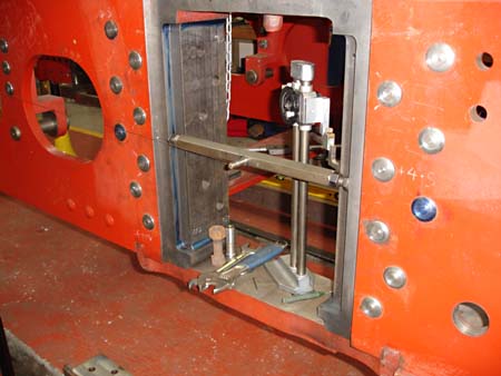
Ten of Fred Bailey's photos show tremendous progress on many fronts. That on the right shows an adjustable beam that allows the centre of the axle to be located from the horns and holds the end of the alignment wire.
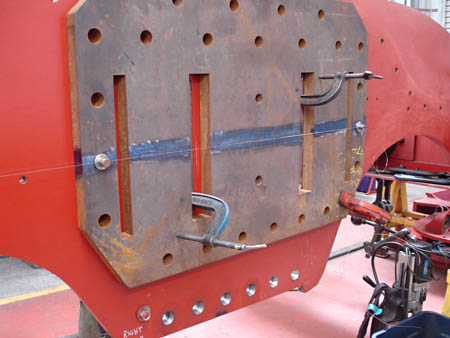
Below left we see a cylinder backplate set up on the frame with the alignment wire from the axle centre as a double check for position. The holes for the fitted bolts have all now been drilled and reamed.
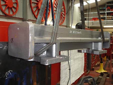
Below right is the motion bracket cast in high grade SG iron. (The casting is upside down in the photo).
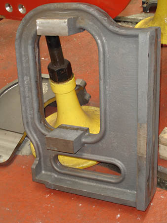
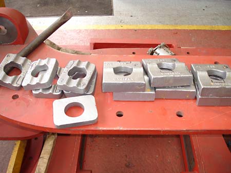
The next two photos show the inside frame stretcher with the valve spindle guide support, in cast steel, and the cast steel special washers and plates that fit to the end of the leading coupled axle leaf springs.
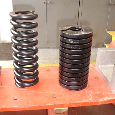
The brake hangers, seen below earlier this month, are now being machined in the main works. The two coil springs show the types used for the bogie (left) - there are 8 of these in the set, and (on the right) the type for the driving axle, of which there are 4 in the set. Because a round section alternative of the latter is not viable, we have bought a spare set due to the likelihood of supplies becoming even more difficult in the future.
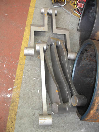
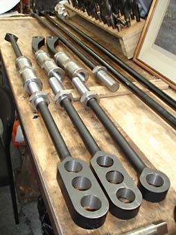
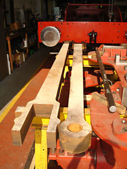
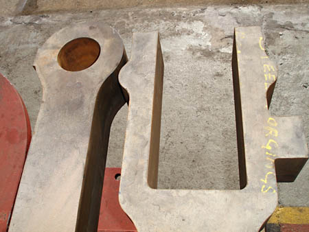
The last three photos below show the brake gear pull rods and slack adjusters; the most recent photos show both connecting rods now water-jet cut, and a close-up of the ends of the connecting rods. The accuracy of the water jet cutting (described in the 9th April report below) is such that a measurement with a vernier across the small end showed just a .006" variation through the thickness of the cut (which is 4.5").
Other recent news includes work on the valve chests, brakes and wheels.
Each component that will make up the valve chests is having its weld preps burned, ground or machined depending on the best and most efficient method to suit each individual part. Most of the brake pins have now been turned, together with a large number of the sacrificial bushes that are pressed into the brake gear components.
Progress is still being made by Ian Riley in Bury on the wheels, with the remaining three bogie wheels now turned. Unfortunately more businesses have gone to the wall of late, giving him problems with getting the heat treatment carried out on the main driving axles, but this should be resolved shortly.
2 October 2009
It has been a while since the last update, so here are some more photos. The first five are from Fred Bailey, and the last two from Derek Hayward.
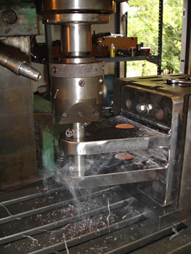
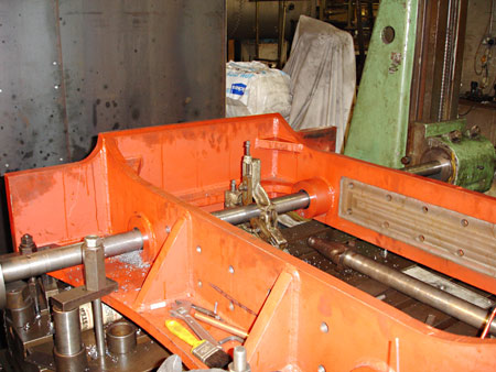
The first photo shows one of the equaliser brackets for the brake cross beams having the pin holes in-line bored on the Milling machine in Atlantic House.
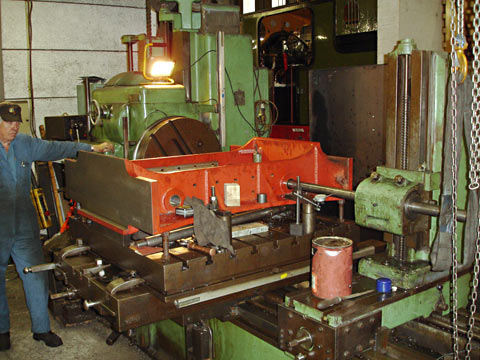
The second shows Derek Barlow operating the large horizontal borer in the main works. He is also in-line boring. The item is the main bogie stretcher and the holes take the pins for the swing links.
The photo on the right is a closer view of this operation. The lathe steady between the bosses that are being bored is to try and make the boring bar more rigid. It is rather long for its diameter.
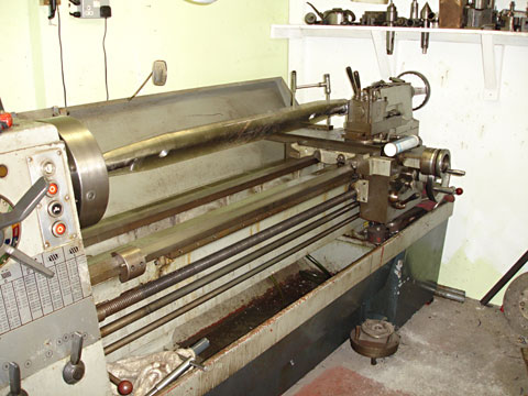
The photo below is a brake cross beam in the lathe in Atlantic House. We are truing the ends that go in the brake hangers.
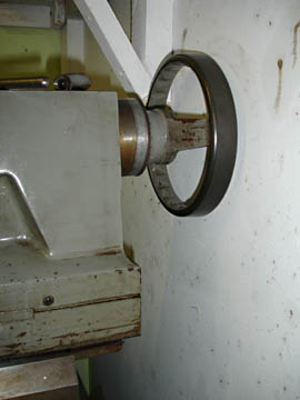
The other photo shows the lathe to be on its limit for length. The handle on the tailstock wheel has been removed as has a part of the shelf bracket, to give us enough length to get these items in.
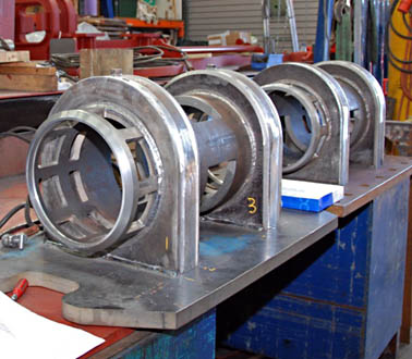
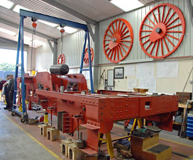
We are just about to place orders for the main driving axleboxes to be machined, along with the coupling and connecting rods. The Manganese liners that fit to the main horns are due back very soon from grinding, so these should be fitted shortly. Progress continues with the valve chest welding and it is coming along well (seen in the photo below at the Behind Bluebell open day on 12 September), although we think the welding rod manufacturers will report a boom year. We are told that we might receive the bogie wheels by mid November, so watch this space. There is more happening than this, but we may be in a position to start assembling some more of it soon. The time is taken in making and obtaining the parts. The assembly usually doesn't take that long. The second photo below (taken from the rear of the loco) shows just how much of the loco frames has been completed.
17 October: Project Funding
Contrary to what you may have read in the railway press, fund-raising continues for this project. We may well receive a sum of money (as yet this is an unknown sum) as a legacy, but we are still well short of the final amount needed to complete this project.
All your donations, gifts, sponsorships etc. are still needed and are gratefully received by those of us actively engaged in trying to move this project forward to a successful conclusion. The extra money now available to the Atlantic project is most welcome, and will expedite the project, not least because it makes it easier to plan purchases and subcontracted work in a logical order without short-term concerns about cash-flow, but it is categorically not sufficient to complete the project.
13 December 2009
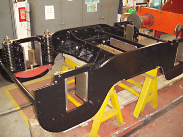
The first photo above shows the assembled bogie (upside down on the trestles).
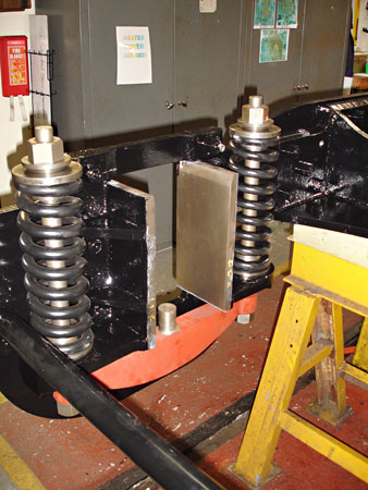
That to the right shows a trial assembly of the springs for the bogie axleboxes
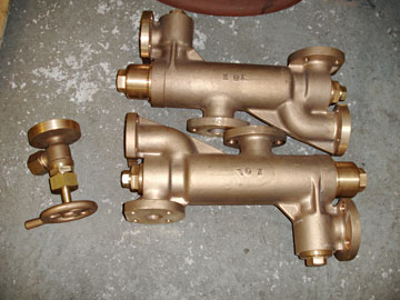
The other photo is of the two injectors plus the steam heat isolating valve, recently purchased, ready machined.
We have also now trial assembled the brake gear to the rear, driving and coupled axles. We have not installed the brake cylinders as yet so the final connections will be made at a later date.
The spring hangers for the coupled wheels, that are also the trunnion bearings for the main brake shaft, are now complete and we are currently working towards getting them not only fitted to the frame, but properly aligned to each other. This task is not made easier by the fact that they are located just at the frame joggle. We are sure that a good deal of fitting was required back in 1911 at this point.


More recent news updates
- 2010 - Cylinders and valve chests fabricated, air brake cylinders completed, bogie and trailing wheelsets completed.
- 2011 - Coupling rods and axleboxes delivered, reverser mechanism completed, crossheads cast.
- 2012 - Valve and cylinder liners fitted - lifting and reversing arms and axlebox crowns delivered - castings for mudhole doors, regulator and whistle valves, reversing shaft clutch, blast-pipe cap, crosshead slippers, 'J' pipe and eight eccentric halves received - Bogie and trailing axle now support the frames - Valve chest and cylinders fitted to frames, covers fitted, and pressure tested.
- 2013 - Cylinders, valves, slidebars and crossheads completed - driving wheels completed - valve gear components delivered - lifting frames constructed.
- 2014 - Weigh (reversing) shaft and air-clutch fitted, axleboxes metalled, machined and fitted, wheel rotators constructed, eccentric rods, valve and reversing gear, pipework for brakes and steam heat completed, locomotive wheeled, cylinders clad and crossheads fitted.
- 2015 - Rolling Chassis completed with all motion erected. Running plates and splashers completed, along with cab sides and front.
- 2016 - Connecting and coupling rods fitted, valves set. Superheater header delivered. Revision of boiler internal pipework completed. Cab roof riveted together and fitted. Mud-hole patches welded into boiler. Flue tubes (with screw ends welded on) delivered.
- 2017 - Major progress on the boiler overhaul, and with the safety valves.
- 2018 - Boiler tubes fitted, tender made mobile, complex parts of the boiler cladding made.
- Most recent news.
Older news updates
- Background and early progress
- September 2001: Repairs to tender chassis.
- More photos of the project (1999-2002).
- March 2002: Modification of front end of tender.
- November 2004: Loco Frames ordered.
- December 2004: Bogie frame components arrive - also Feb.2005 news report.
- 2005 - Loco main frames arrive - tender frames nearly completed - start of construction of the shed.
- 2006 - Loco driving wheel castings delivered - drilling of the main frames and hornguides - building of the shed completed.
- 2007 - Main locomotive frames erected.
- 2008 - Components for the cylinders and valve chest delivered - frames riveted - forged billets for connecting and coupling rods delivered.
Project Funding
A fund raising appeal for the cash required to complete the project was launched in 2000, and a combination of gifts made via the Bluebell Railway Trust, and standing orders set up to provide a steady income to the project have now made over a third of the total available. Whilst this has provided funding for the present work, more is going to be needed to complete the project, and the best way in which you can help is by setting up a small, regular, standing order to the Bluebell Railway Trust under Gift Aid, since this enables the Trust to reclaim the basic rate tax you have paid, and (if you are a higher rate tax-payer) enables you to reclaim some tax as well.


Return to BRPS Home Page,
to the Timetable or to Special
Events
Atlantic Project - Background - Completion and launch - Next Projects: 'Normandy' and the Adams Radial Tank
Visitor Info. -
Museum -
Trust -
Catering -
Contacts -
What's New -
Projects -
Locos -
Carriages & Wagons -
Signals -
History -
Other -
Links -
Search -
FAQ
Why not become a BRPS Member? -
Get more involved as a Volunteer
Your ideal Film/TV location?
 Photos from Fred Bailey, Malcolm Place and Derek Hayward.
Page maintained by Richard Salmon.
© Copyright BRPS. Privacy Policy
|
